

Coriolis Type Flow Meter Advantages
It has high measurement accuracy, standard accuracy 0.2%; And the measurement is not affected by the physical properties of the medium.
Coriolis type flow meter provide a direct mass flow measurement without the addition of external measurement instruments. While the volumetric flow rate of the fluid will vary with changes in density, the mass flow rate of fluid is independent of density changes.
There is no moving parts to wear and need to be replaced. These design features reduce the need for routine maintenance.
The Coriolis mass flow meter is insensitive to viscosity, temperature and pressure.
The Coriolis flow meter can be configured to measure positive or reverse flow.
Flow meters are operated by flow characteristics such as turbulence and flow distribution. Therefore, upstream and downstream direct pipe operating requirements and flow regulation requirements are not required.
The Coriolis flow meter does not have any internal obstacles, which may be damaged or blocked by viscous slurry or other types of particulate matter in the flow.
It can take measurement of high viscosity fluids, such as crude oil, heavy oil, residual oil and other liquids with higher viscosity.
● Petroleum, such as crude oil, coal slurry, lubricant and other fuels.
● High viscosity materials, such as asphalt, heavy oil and grease;
● Suspended and solid particulate matter materials, such as cement slurry and lime slurry;
● Easy-to-solidified materials, such as asphalt
● Accurate measurement of medium- and high-pressure gases, such as CNG oil and gas
● Micro-flow measurements, such as fine chemical and pharmaceutical industries;
Table 1: Coriolis Mass Flow Meter Parameters
| Flow accuracy | ±0.2% Optional ±0.1% |
| Diameter | DN3~DN200mm |
| Flow repeatability | ±0.1~0.2% |
| Density measuring | 0.3~3.000g/cm3 |
| Density accuracy | ±0.002g/cm3 |
| Temperature measuring range | -200~300℃ (Standard Model -50~200℃) |
| Temperature accuracy | +/-1℃ |
| Output of current loop | 4~20mA; Optional signal of flow rate/Density/Temperature |
| Output of frequency/pulse | 0~10000HZ; Flow signal (Open collector) |
| Communication | RS485, MODBUS protocol |
| Power supply of transmitter | 18~36VDC power≤7W or 85~265VDC power 10W |
| Protection class | IP67 |
| Material | Measuring tube SS316L housing:SS304 |
| Pressure rating | 4.0Mpa (Standard pressure) |
| Explosion-proof | Exd(ia) IIC T6Gb |
| Enviroment Specifications | |
| Ambient temperature | -20~-60℃ |
| Enviroment humidity | ≤90%RH |
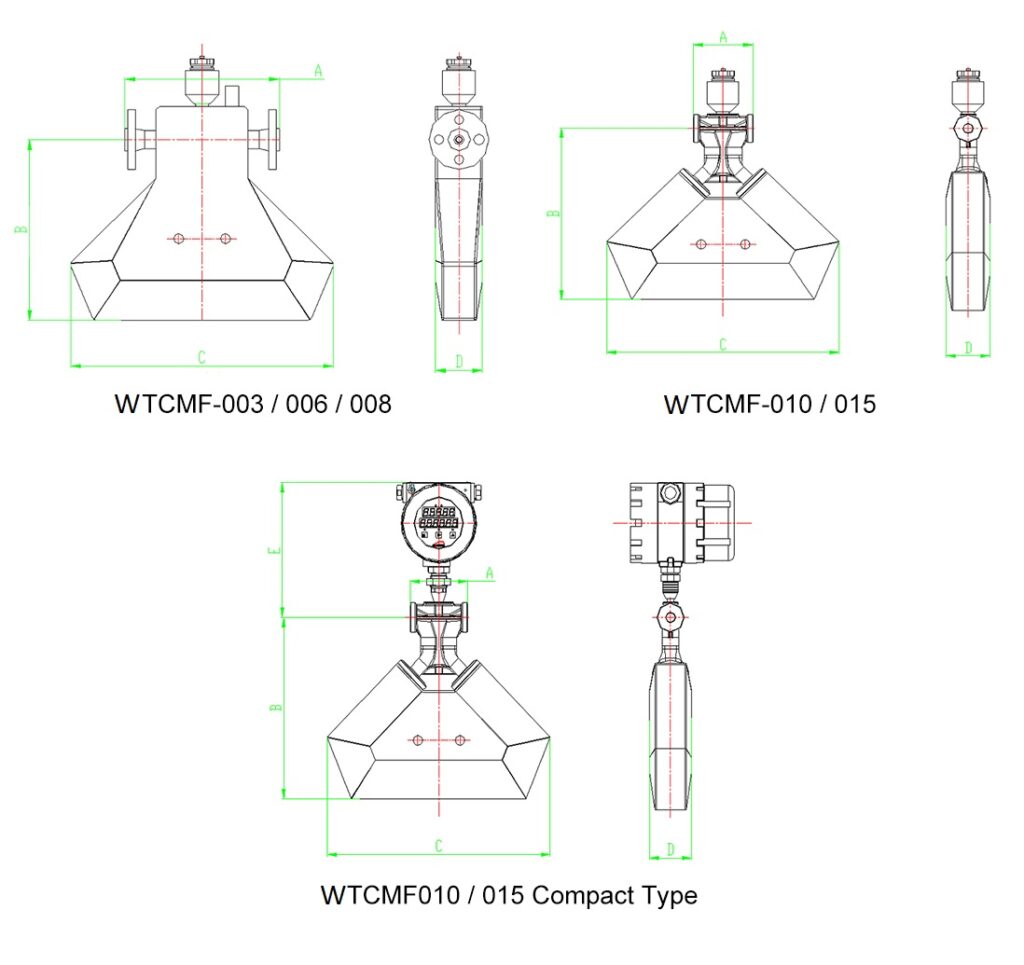
Table 2: Coriolis Mass Flow Meter Dimension
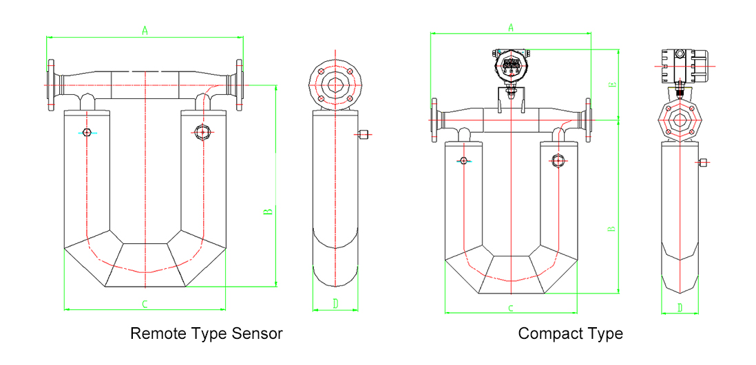
| Model | A | B | C | D | E | NW(only sensor) |
| mm | mm | mm | mm | mm | kg | |
| WTCMF-020 | 250 | 448 | 500 | 89 | 233 | 17 |
| WTCMF-025 | 550 | 500 | 445 | 108 | 238 | 17.5 |
| WTCMF-032 | 550 | 500 | 445 | 108 | 240 | 24 |
| WTCMF-040 | 600 | 760 | 500 | 140 | 245 | 32 |
| WTCMF-050 | 600 | 760 | 500 | 140 | 253 | 36 |
| WTCMF-080 | 850 | 1050 | 780 | 220 | 315 | 87.5 |
| WTCMF-100 | 1050 | 1085 | 840 | 295 | 358 | 165 |
| WTCMF-150 | 1200 | 1200 | 950 | 320 | 340 | 252 |
| WTCMF-200 | 1200 | 1193 | 1000 | 400 | 358 | 350 |
| Model | A | B | C | D | E | Nw |
| mm | mm | mm | mm | mm | kg | |
| WTCMF-003 | 178 | 176 | 250 | 54 | 244 | 48 |
| WTCMF-006 | 232 | 263 | 360 | 70.5 | 287 | 8.1 |
| WTCMF-00B | 232 | 275 | 395 | 70.5 | 290 | 82 |
| WTCMF-010 | 95 | 283 | 370 | 70.5 | 242 | 65 |
| WTCMF-015 | 95 | 302 | 405 | 70.5 | 242 | 65 |
Table 3: Coriolis Mass Flow Meter Flow Range
| Specification | DN (mm) | Flow range (kg/h) | Zero stability, kg/h | NW (kg) | GW (kg) | ||
| 0.2% | 0.15% | 0.1% | |||||
| WTCMF-003 | 3 | 0~96~120 | 0.018 | 0.012 | 0.012 | 8 | 19 |
| WTCMF-006 | 6 | 0~540~660 | 0.099 | 0.066 | 0.066 | 12 | 22 |
| WTCMF-008 | 8 | 0~960~1200 | 0.18 | 0.12 | 0.12 | 12 | 23 |
| WTCMF-010 | 10 | 0~1500~1800 | 0.27 | 0.18 | 0.18 | 11 | 24 |
| WTCMF-015 | 15 | 0~3000~4200 | 0.63 | 0.42 | 0.42 | 12 | 25 |
| WTCMF-020 | 20 | 0~6000~7800 | 1.17 | 0.78 | 0.78 | 20 | 34 |
| WTCMF-025 | 25 | 0~10200~13500 | 2.025 | 1.35 | 1.35 | 21 | 35 |
| WTCMF-032 | 32 | 0~18000~24000 | 3.6 | 2.4 | 2.4 | 27 | 45 |
| WTCMF-040 | 40 | 0~30000~36000 | 5.4 | 3.6 | 3.6 | 35 | 55 |
| WTCMF-050 | 50 | 0~48000~60000 | 9 | 6 | 6 | 40 | 60 |
| WTCMF-080 | 80 | 0~120000~160000 | 24 | 16 | 16 | 90 | 150 |
| WTCMF-100 | 100 | 0~222000~270000 | 40.5 | 27 | 27 | 170 | 245 |
| WTCMF-150 | 150 | 0~480000~600000 | 90 | 60 | 60 | 255 | 350 |
Table 4: Coriolis Mass Flow Meter Mode Selection
| WTCMF | XXX | X | X | X | X | X | X | X | X | X | |
| Caliber (mm) | DN3mm-DN200 mm | ||||||||||
| Nominal Pressure | 0.6Mpa | 1 | |||||||||
| 1.0Mpa | 2 | ||||||||||
| 1.6Mpa | 3 | ||||||||||
| 2.5Mpa | 4 | ||||||||||
| 4.0Mpa | 5 | ||||||||||
| Others | 6 | ||||||||||
| Connection | Flange | 1 | |||||||||
| Tri-clamp(Sanitary) | 2 | ||||||||||
| Thread | 3 | ||||||||||
| Others | 4 | ||||||||||
| Accuracy | 0.1 | 1 | |||||||||
| 0.2 | 2 | ||||||||||
| Temperature | – 200℃~200℃ | 1 | |||||||||
| -50℃~200℃ | 2 | ||||||||||
| -50℃~300℃ | 3 | ||||||||||
| Structure Type | Compact/Integral | 1 | |||||||||
| Remote | 2 | ||||||||||
| Power Supply | AC220V | A | |||||||||
| DC24V | D | ||||||||||
| Output Signal | 4-20mA/Pulse,RS485 | A | |||||||||
| 4-20mA,HART | B | ||||||||||
| Others | C | ||||||||||
| Ex-proof | Without Ex-proof | 0 | |||||||||
| With Ex-proof | 1 | ||||||||||
| Process Connection | DIN PN10 | 1 | |||||||||
| DIN PN16 | 2 | ||||||||||
| DIN PN25 | 3 | ||||||||||
| DIN PN40 | 4 | ||||||||||
| ANSI 150# | A | ||||||||||
| ANSI 300# | B | ||||||||||
| ANSI 600# | C | ||||||||||
| JIS 10K | D | ||||||||||
| JIS 20K | E | ||||||||||
| JIS 40K | F | ||||||||||
| Others | G | ||||||||||
Installation
1. Basic Requirements on installation
(1)Flow direction should be in accordance with CMF sensor flow arrow.
(2)Properly supporting is required for preventing tubes vibrating.
(3)If a strong pipeline vibration is inevitable, it is recommended to use a flexible tube to isolate the sensor from the pipe.
(4)Flanges should be kept parallel and their center points should be located on the same axis to avoid subsidiary force generation.
(5)Installation vertically, make the flow from the bottom up when measuring, meanwhile, the meter should not be installed on the top to prevent air getting trapped inside the tubes.
2.Installation Direction
In order to ensure the reliability of the measurement, the ways of installation should consider the following factors:
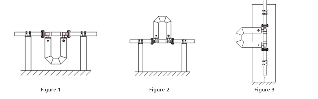
(1)The meter should be installed downward when measuring liquid flow (Figure 1), so that air cannot get trapped inside the tubes.
(2)The meter should be installed upward when measuring gas flow (Figure 2), so that liquid cannot get trapped inside the tubes.
(3)The meter should be installed sideward when the medium is turbid liquid (Figure 3) to avoid particulate matter accumulated in the measuring tube. The flow direction of medium goes from the bottom up through the sensor.