

Gas Turbine Flow Meter Advantages and Disadvantages
Gas turbine flow meter is with advanced rectification technology and dust-proof structure. It is with built-in temperature and pressure sensors which can achieve automatically compensation to make sure high accuracy. Gas turbine flow meter provides good solution for custody transfer between parties.
Compared with precession vortex flow meter, gas turbine flow meter is with low pressure loss, low initiating flow and wider measurement range. The display of gas turbine flow meter support to rotate 350°, easy to read data in different directions.
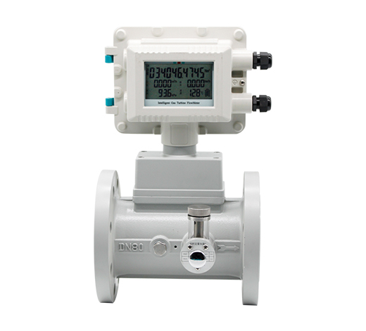
Table 1: Gas Turbine Flow Meter Parameters
| Nominal Diameter | DN25-DN400 |
| Nominal Pressure | 1.0Mpa/1.6Mpa/2.5Mpa/4.0Mpa |
| Range Ratio | Max 40:1 (under P=101.325Kpa,T=293.15K) |
| Accuracy | 1.5% (Standard), 1.0 (Optional) |
| Repeatability | Better than 0.2% |
| Explosion Proof | ExiallCT6Ga |
| Protection | IP65 |
| Shell Material | Aluminum Alloy/Carbon Steel/Stainless Steel |
| Power Supply | 3.6V Lithum Battery Powered External power DC18-30V |
| output Signal | 4-20mA,Pulse,Alarm |
| Communication | RS485 Modbus RTU |
Table 2: Gas Turbine Flow Meter Dimension
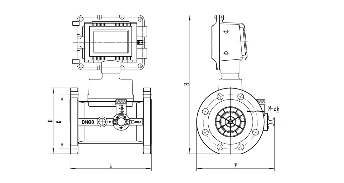
| Size | L | D | K | N-φh | H | W | Remarks |
| DN25(1″) | 200 | 115 | 85 | 4-φ14 | 335 | 200 | 1.Flange information according to PN16 GB9113.1-2000
2.Other flanges are available |
| DN40(1½”) | 200 | 150 | 110 | 4-φ18 | 365 | 230 | |
| DN50(2″) | 150 | 165 | 125 | 4-φ18 | 375 | 275 | |
| DN80(3″) | 240 | 200 | 160 | 8-φ18 | 409 | 280 | |
| DN100(4″) | 300 | 220 | 180 | 8-φ18 | 430 | 285 | |
| DN150(6″) | 450 | 285 | 240 | 8-φ22 | 495 | 370 | |
| DN200(8″) | 600 | 340 | 295 | 12-φ22 | 559 | 390 | |
| DN250(10″) | 750 | 405 | 355 | 12-φ26 | 629 | 480 | |
| DN300(12″) | 900 | 460 | 410 | 12-φ26 | 680 | 535 | |
| DN400(16″) | 1200 | 580 | 525 | 16-φ30 | 793 | 665 |
Table 3: Gas Turbine Flow Meter Flow Range
| DN (mm/inch) |
Model | Flow specification | Flow range (m3/h) | Qmin (m3/h) | Max.pressur e loss (Kpa) | Shell material | Weight(kg) |
| DN25(1″) | WTWG-25(A) | G50 | 5-50 | ≤1 | 1 | ≤1.6MPa Aluminum Alloy ≥2.0MPa Carbon steel or SS304 |
7 |
| DN40(1½″) | WTWG-40(A) | G60 | 6-60 | ≤1 | 1 | 8 | |
| 50(2″) | WTWG-50(A) | G40 | 6.5-65 | ≤1.3 | 0.9 | 8.5 | |
| WTWG-50(B) | G65 | 8-100 | ≤1.6 | 0.8 | |||
| WTWG-50(C) | G100 | 10-160 | ≤2.4 | 2.0 | |||
| 80(3″) | WTWG-80(A) | G100 | 8-160 | ≤2.4 | 1.0 | 9.5 | |
| WTWG-80(B) | G160 | 13-250 | ≤3.0 | 1.6 | |||
| WTWG-80(C) | G250 | 20-400 | ≤5.0 | 2.0 | |||
| 100(4″) | WTWG-100(A) | G160 | 13-250 | ≤3.3 | 1.0 | 15 | |
| WTWG-100(B) | G250 | 20-400 | ≤4.2 | 1.6 | |||
| WTWG-100(C) | G400 | 32-650 | ≤6.7 | 1.8 | |||
| 150(6″) | WTWG-150(A) | G400 | 32-650 | ≤7.8 | 1.6 | 27 | |
| WTWG-150(B) | G650 | 50-1000 | ≤10 | 2.0 | |||
| WTWG-150(C) | G1000 | 80-1600 | ≤12 | 2.3 | |||
| 200(8″) | WTWG-200(A) | G650 | 50-1000 | ≤13 | 1.6 | Carbon Steel or SS304 | 45 |
| WTWG-200(B) | G1000 | 80-1600 | ≤16 | 2.0 | |||
| WTWG-200(C) | G1600 | 130-2500 | ≤20 | 2.2 | |||
| 250(10″) | WTWG-250(A) | G1000 | 80-1600 | ≤20 | 1.2 | 128 | |
| WTWG-250(B) | G1600 | 130-2500 | ≤22 | 2.0 | |||
| WTWG-250(C) | G2500 | 200-4000 | ≤25 | 2.3 | |||
| 300(12″) | WTWG-300(A) | G1600 | 130-2500 | ≤22 | 1.6 | 265 | |
| WTWG-300(B) | G2500 | 200-4000 | ≤25 | 2.0 | |||
| WTWG-300(C) | G4000 | 320-6500 | ≤35 | 2.3 | |||
| 400(16″) | WTWG-400(A) | G1600 | 300-2500 | ≤25 | 1.8 | 380 | |
| WTWG-400(B) | G2500 | 500-4000 | ≤35 | 2.0 | |||
| WTWG-400(C) | G4000 | 600-8000 | ≤40 | 2.3 |
Table 4: Gas Turbine Flow Meter Model Selection
| WTWG | Parameters | XXX | X | X | X | X | X | X | X |
| Size (mm) | DN25-DN400mm | ||||||||
| Accuracy | 1.5% (standard) | 1 | |||||||
| 1.0% | 2 | ||||||||
| Nominal | 1.0MPa | 1 | |||||||
| Pressure | 1.6MPa | 2 | |||||||
| 2.5MPa | 3 | ||||||||
| 4.0MPa | 4 | ||||||||
| Others | 5 | ||||||||
| Body Material | Aluminum Alloy (For size below DN150mm) | 1 | |||||||
| Carbon Steel | 2 | ||||||||
| Stainless Steel | 3 | ||||||||
| Output/Communication | Pulse+4-20mA | 1 | |||||||
| Pulse+4~20mA+485 | 3 | ||||||||
| Pulse+4~20mA+HART | 4 | ||||||||
| Power Supply | Battery Powered + External Power DC24V (two-wire) | 1 | |||||||
| Battery Powered +External Power DC24V (three-wire) | 2 | ||||||||
| Ex-proof | With | 1 | |||||||
| Without | 2 | ||||||||
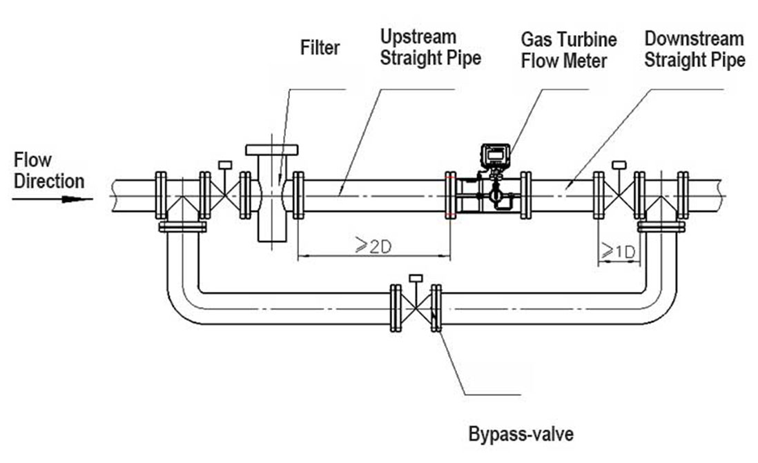
Installation Requirement for Gas Turbine Flow Meter
In order to obtain a stable and accurate flow measurement, it is very important that the flow meter is installed correctly in the pipe system
Flow meter need to be installed on horizontal pipeline. The inner diameter of the flow meter need to be as same as inner diameter of pipeline, and the axis of the flow meter should be concentric with the axis of the pipeline during installation
Recommend to install indoors. If need to install outdoors, please make good protection from direct sunlight and rain
In order to ensure the normal use of the medium is not affected when the flow meter is overhauled, a shut-off valve should be installed on the upstream and downstream of the flow meter. A bypass pipeline should be provided. The flow control valve must be installed downstream of the flow meter, and the upstream valve must be fully open when the flow meter is used.
Gas Turbine Flow Meter Maintenance
Gas turbine flow meter need to do oil filling operation regularly to ensure bearings work smoothly.
There’s oil filling operation indication on each Woteck gas turbine flow meter’s body. Follow the indication to do oil filling regularly is fine.